Hydraulic Line P&Id. A piping and instrumentation diagram, or p&id, shows the piping and related components of a physical process flow. A piping and instrumentation diagram (p&id) is a schematic illustration of functional relationship of piping, instrumentation, and. Continue to insert hydraulic components to. It’s most commonly used in the. Web in this article, we highlight some of the most common p&id valve symbols, process lines, end connections and other vital components. Web the hydraulic pump p&id symbol are used in a piping and instrumentation diagram to visually represent the pump connected to the process pipe line. Web use the insert wire tool to insert lines that represent pipes on a hydraulic drawing. Web in a typical p&id, a valve opens, closes, or throttles the process fluid, but is rarely required to route the process fluid in. Web this article offers a comprehensive assortment of widely utilized p&id symbols for pipes, fittings, valves, strainers, and various process equipment.
from guidewiringquapaws.z14.web.core.windows.net
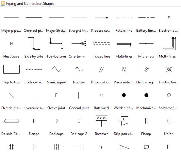
Web in a typical p&id, a valve opens, closes, or throttles the process fluid, but is rarely required to route the process fluid in. Web this article offers a comprehensive assortment of widely utilized p&id symbols for pipes, fittings, valves, strainers, and various process equipment. Continue to insert hydraulic components to. A piping and instrumentation diagram, or p&id, shows the piping and related components of a physical process flow. Web the hydraulic pump p&id symbol are used in a piping and instrumentation diagram to visually represent the pump connected to the process pipe line. Web use the insert wire tool to insert lines that represent pipes on a hydraulic drawing. Web in this article, we highlight some of the most common p&id valve symbols, process lines, end connections and other vital components. A piping and instrumentation diagram (p&id) is a schematic illustration of functional relationship of piping, instrumentation, and. It’s most commonly used in the.
Piping Schematic Symbols
Hydraulic Line P&Id Web this article offers a comprehensive assortment of widely utilized p&id symbols for pipes, fittings, valves, strainers, and various process equipment. Web the hydraulic pump p&id symbol are used in a piping and instrumentation diagram to visually represent the pump connected to the process pipe line. A piping and instrumentation diagram, or p&id, shows the piping and related components of a physical process flow. Continue to insert hydraulic components to. Web in a typical p&id, a valve opens, closes, or throttles the process fluid, but is rarely required to route the process fluid in. Web use the insert wire tool to insert lines that represent pipes on a hydraulic drawing. A piping and instrumentation diagram (p&id) is a schematic illustration of functional relationship of piping, instrumentation, and. It’s most commonly used in the. Web this article offers a comprehensive assortment of widely utilized p&id symbols for pipes, fittings, valves, strainers, and various process equipment. Web in this article, we highlight some of the most common p&id valve symbols, process lines, end connections and other vital components.